What is Channel Puncturing?
Channel puncturing allows Wi-Fi 7 access points (APs) to exclude specific subchannels affected by interference or noise, while efficiently utilizing the remainder spectrum. This ensures that maximum channel width is utilized and interference on a small chunk of channel width does not result in under utilization of the remainder large chunk of usable channel width.
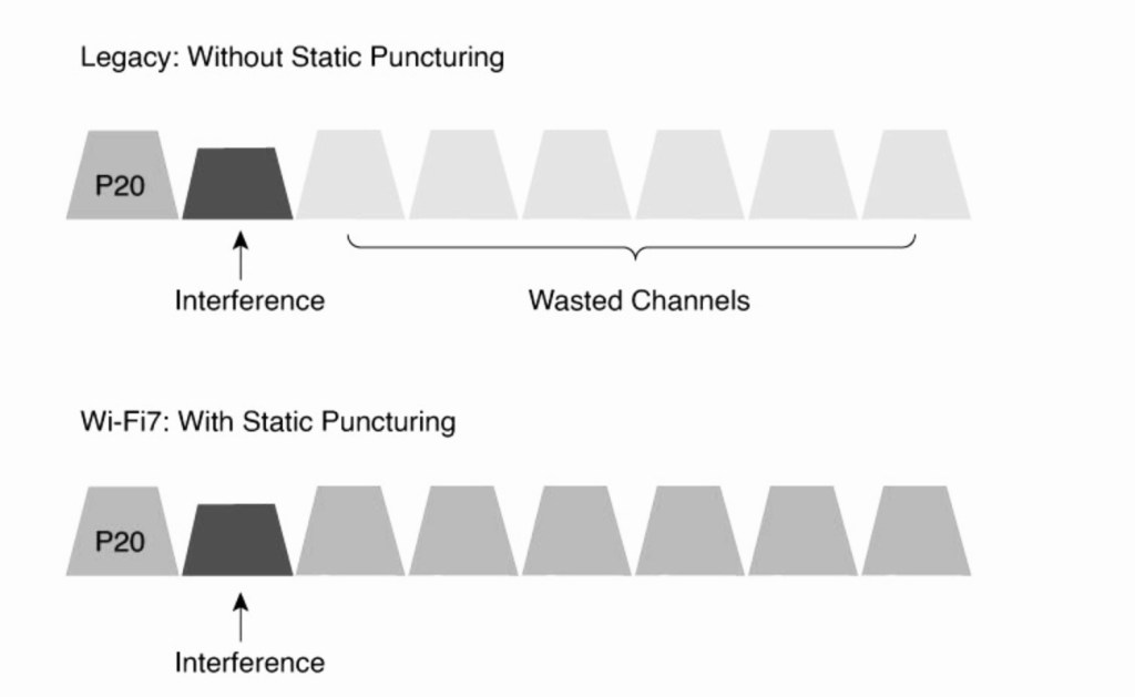
Legacy channel width adjustment
In a legacy Wi-Fi scenario, wherein the AP/client are operating in 160 MHz channel width and interference is introduced on specific sub-channel the remaining channels are wasted while with static puncturing except for the interfering sub-channel all remaining channels in 160 MHz channel width can be used for data transmission.
Channel Puncturing Advertisement in Management and Data Frames
Verify the channel puncturing in Beacon, Association Response and data frame.
Beacon Frame- wlan.fc.type_subtype == 0x0008
Association Frame- wlan.fc.type_subtype == 0x0001
Data Frame- wlan.fc.type_subtype == 0x0028
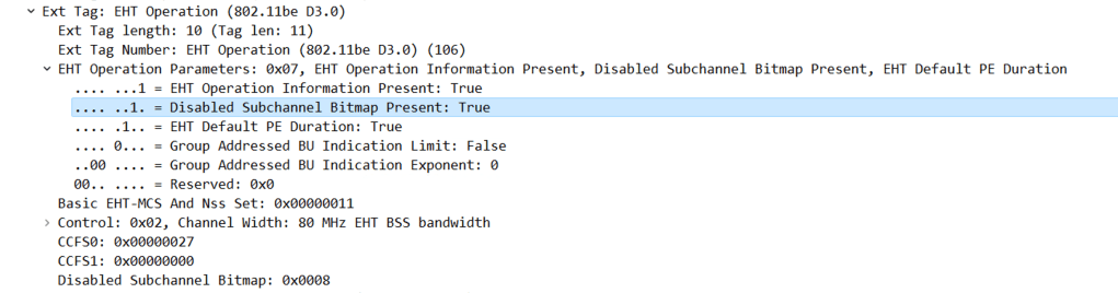
Beacon– When channel puncturing is enabled, it is advertised in the Beacon frame under EHT Operations parameters.
The below scenario shows the AP is operating in 80 MHz channel width with primary channel as 37 and punctured sub-channel 39
IEEE 802.11 Wireless management>Tagged Parameters>EHT Operation>EHT Operation parameters.
- Disabled Subchannel Bitmap Present- True
- Channel width- 80 MHz
- CCFS0 (Channel Center Frequency Segment 0)- 0x00000027 (reprsents hex equivalent of the punctured subchannel 39)
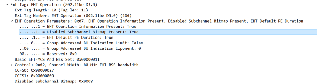
Association Response- When channel puncturing is enabled, it is advertised in the Beacon frame under EHT Operations parameters.
IEEE 802.11 Wireless management>Tagged Parameters>EHT Operation>EHT Operation parameters.
- Disabled Subchannel Bitmap Present- True
- Channel width- 80 MHz
- CCFS0 (Channel Center Frequency Segment 0)- 0x00000027 (reprsents hex equivalent of the punctured subchannel 39)
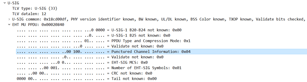
QoS Data
In the Radiotap Header of the QoS Data frame, we can find the punctured channel information in EHT MU PPDU in the U-SIG field.
RadioTap Header>U-SIG>EHT-MU PPDU
Punctured Channel Information-0x04 (Represents Punctured channels)
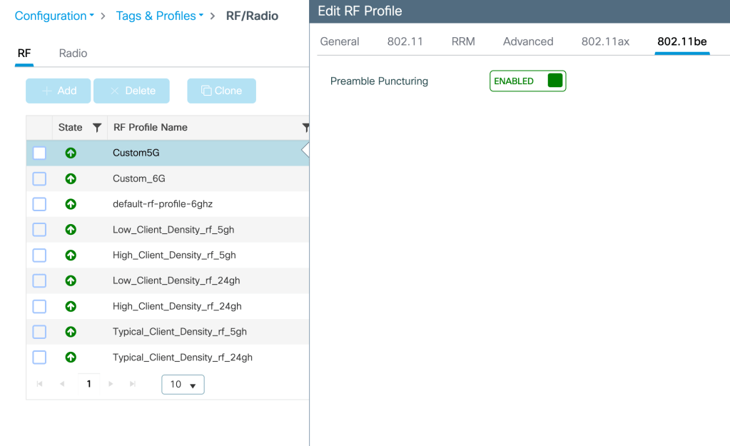
How to configure Puncturing in 9800 WLC?
Puncturing can be enabled in RF profile associated to the AP radio under- Configuration>Tags and Profiles>RF/Radio>RF>Add Profile>802.11 be>Enable Preamble Puncturing
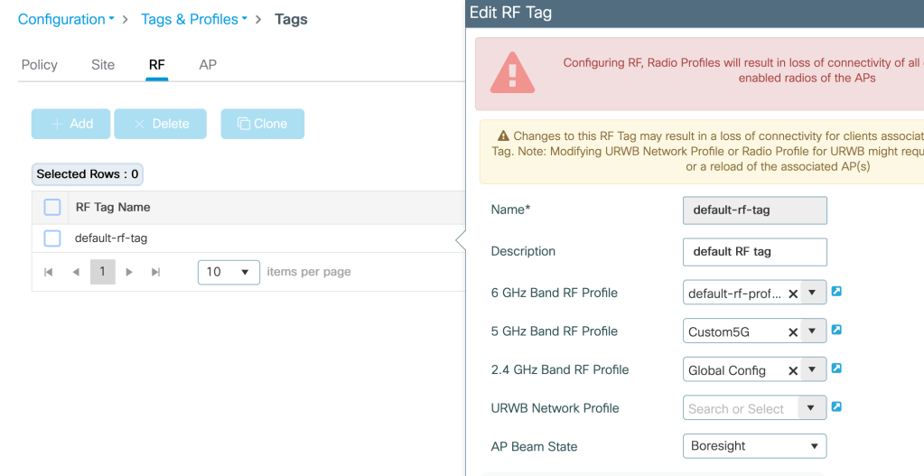
Assign this RF profile to the RF site tag mapped to the AP under test-
Configuration>Tags and Profiles>Tags>(2.4G/5G/6G) Band RF Profile
Related Blogs–
Dynamic Frequency Selection (DFS)
Dynamic Channel Assignment (DCA)
Dynamic Bandwidth Selection (DBS)
Cisco Configuration Guides
How to configure 9800 WLC for max throughput and max spatial streams?
