This Chapter will cover the basics of radio frequency signal characteristics and the signal behavior.
- The Radio Frequency (RF) signal functions at the physical layer (Layer 1) of the OSI model
- An RF signal starts as an electrical alternating signal sent through a copper conductor out of the antenna element as an electromagnetic wave.
- The electromagnetic wave propagates away from the antenna element as a sine wave which has certain properties like amplitude, wavelength, frequency, phase. Similarly it also has certain propagation behaviors like absorption, reflection, scattering, refraction, diffraction, amplification and attenuation.
- Wavelength: Distance between two successive crests or troughs. (peak to peak)

- Wavelength is inversely proportional to frequency.
- Wavelength=Speed of light/Frequency
- Higher frequency signals attenuate faster than lower frequency signals reason being the amount of energy captured by high frequency antenna is smaller than that captured by a low frequency antenna.
- 2.4 GHz signals will attenuate slower than 5 GHz signal while propagating hence 2.4 GHz radio coverage area is typically larger than the 5 GHz radio coverage area.
- Frequency: Number of oscillations in a second
- Amplitude: Signal strength/power.
- Transmit Amplitude: Initial amplitude leaving the radio transmitter.
- Received Amplitude: The RSSI of the received signal.
- Phase: Relationship between the position of the amplitude crests and troughs of two waveforms.
- Two waves in phase (0 phase difference) combine the resulting amplitude is the sum of the two while if two out of phase (180 phase difference) waves combine they cancel out each other.
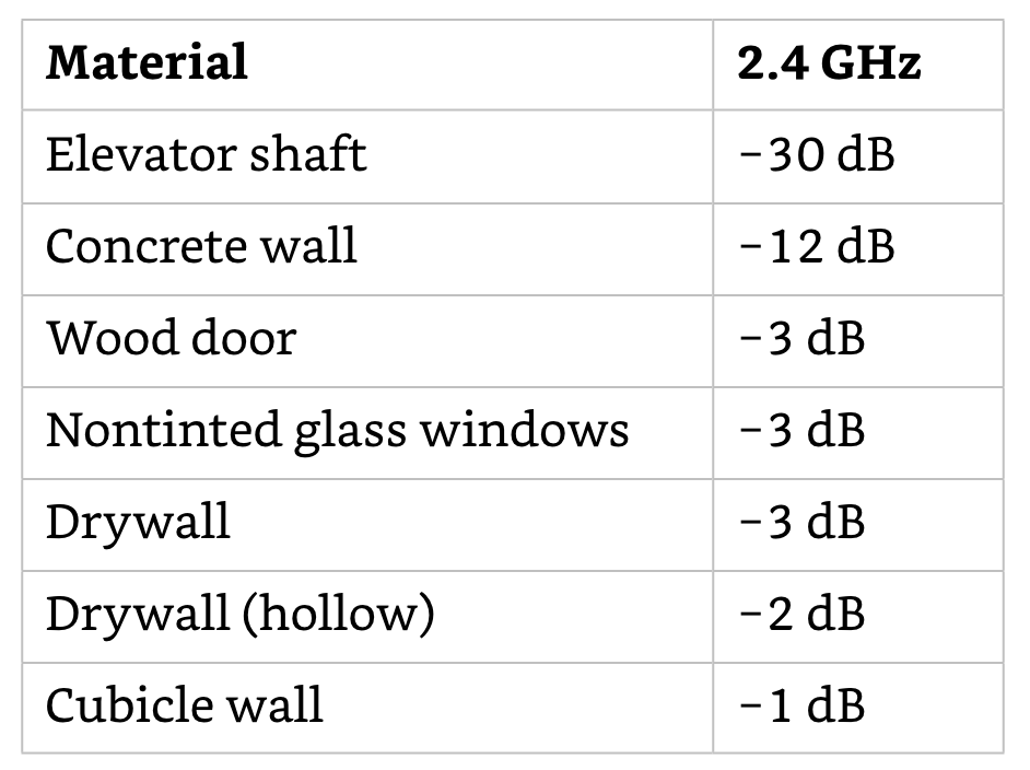
- Absorption: Attenuation in the signal power as it passes through various medium while propagating.
- Reflection: Bouncing of a wave of the surface as it hits a smooth object that is larger than the wave itself.
- Skywave Reflection: Reflection occurring wherein the signal has a large wavelength.
- Microwave Reflection: Reflection occurring wherein the signal has smaller wavelengths.
- Scattering: Multiple reflections of the electromagnetic signal when its wavelength is larger than the medium the signal is reflecting of or passing through.
- Refraction: Bending of an RF signal as it passes through a medium with a different density, causing change in direction of the wave. Common causes being water vapor, changes in air pressure and changes in air temperature.
- Diffraction: Bending of an RF signal around an object
- Loss/Attenuation: Decrease of amplitude or signal strength.
- Free Space Path loss: Loss of signal Strength caused by natural broadening of the waves called a beam divergence.

- Importance of FSPL: Every radio device has receiver sensitivity level which implies that the receiver can receiver a signal down to a certain fixed amplitude level. For the receiver to be able hear the signal the signal should be strong to be heard above the noise floor.
- Multipath: Propagation phenomenon that results in two or more paths of a signal arriving at a receiving antenna at same time. The time differential between the multiple paths is known as the delay spread.
- Upfade: Increased signal strength when the multiple reflected signals arrive at the receiver at the same time and in phase. (0 to 120 degrees difference in phase)
- Downfade: Decreased signal strength when multiple RF signal paths arrive at the receiver at the same time and are out of phase. (121 to 179 degrees out of phase)
- Nulling: Complete signal cancellation when the signals are 180 degrees out of phase.
- Gain (Amplification): Increase in signal strength. Active Gain: Increase in signal strength using an amplifier. Passive Gain: Increase in signal strength achieved by focussing the RF signal with the use of an antenna.
- Amplitude measurement: Spectrum analyzer is used to analyze the signal in frequency domain while oscilloscope is used to analyze the signal in time domain.
